- Customer Letter/ Warranty
- 1.1 Scope
- 1.2 Operating principle
- 1.3 Construction
- 2.1 Gas conveyed
- 2.2 Working conditions
- 2.2.1 Speed of rotation
- 2.2.2 Pressure
- 2.2.3 Temperature
- 3.1 Handling
- 3.2 Storage
- 3.2.1 Bearing storage
- 3.2.2 Preservation of the compression chamber
- 4.1 On-site positioning of blower
- 4.2 Changing the inlet/outlet arrangement
- 4.3 Coupling
- 4.3.1 Direct coupling
- 4.3.2 Belt drive coupling
- 4.4 Direction of rotation – air flow direction
- 4.5 System piping
- 4.5.1 Inlet pipe
- 4.5.2 Outlet pipe
- 4.6 Check valve
- 4.7 Safety valve
- 4.8 Electrical connection
- 5.1 Preliminary controls
- 5.2 Start-up
- 5.2.1 First start-up
- 5.2.2 Normal start-ups
- 5.3 Operating checks
- 5.3.1 Daily checks
- 5.3.2 Check after first 50 hours
- 5.3.3 Check every 500 hours
- 5.4 Stopping the blower
- 6.1 Preventive maintenance
- 6.1.1 Oil change
- 7.0 Troubleshooting
- 8.1 Blower disassembly
- 9.1 Blower in operation
- 9.2 Before any blower service
- 9.3 During blower service
- 10.1 Oil type
- 10.2 Oil viscosity
- 10.3 Recommended oils
- 10.4 Minimum working temperature
Table of Contents
1.1 Scope
This manual applies to Rotary Blowers of the TL Series from size 10 to size 900, both in horizontal (H) and vertical (V) versions.
1.2 Operating principle
TL Series Blowers are positive displacement blowers comprising two conjugate shaped Tri-Lobe rotors which rotate inside a “figure 8” shaped body. The incoming gas is trapped in the space that forms between the body (figure 1a, 1b) and discharged via the outlet (figure 1c, 1d). The operating pressure is generated by the resistance met by the gas exiting the unit. The capacity is proportional to the speed of rotation and is almost constant when the operating pressure varies.
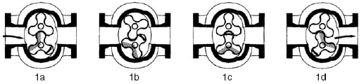
Fig. 1
1.3 Construction
The TL Series Blower is engineered for the smoothest possible flow of air, resulting inlower pulsation and noise.
The body is closed at both ends by end plates in which the housings for the seals and bearings are located. The rotors are synchronized by a pair of timing gears having helical, hardened and ground teeth. The shafts have labyrinth seals; gas leaks are collected in special air spaces in the covers and are discharged into the atmosphere. Two sumps are mounted on the covers which act as oil sumps for splash lubrication of the bearings and the synchronizing gears. The gears are secured on the shafts through conical coupling under oil pressure.
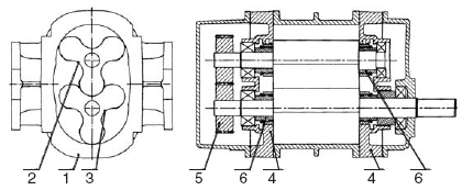
Fig. 2
| Number | Description |
|---|---|
| 1 | Body |
| 2 | Rotor |
| 3 | Rotor |
| 4 | End Plates |
| 5 | Gears |
| 6 | Labyrinth Seals |
2.1 Gas conveyed
The blower can be used to convey inert gases such as air, nitrogen or other gases which are compatible with the lubricating oil and with the materials used in the construction of the blower.
WARNING: The blower cannot be used to convey gases which are explosive, toxic or in any way dangerous.
NOTE: To convey special gases consult Blower Engineering.
2.2 Working conditions
2.2.1 Speed of rotation
The maximum speed of rotation is shown in Table I. The minimum speed of rotation depends on the maximum allowed differential temperature.
2.2.2 Pressure
The inlet pressure ranges from 3 psig (20.7 kPa) to 15 psig (103.4 kPa). The maximum differential pressure is shown in Table I, and depends on the size of the blower. The maximum compression ratio for all sizes of blowers is 2.
2.2.3 Temperature
The inlet temperature of the gas ranges from -13ºF (-25ºC) to 122ºF (50ºC). The maximum differential temperature allowed is shown in Table I, and depends on the size of the blower. The maximum temperature of the gas allowed at the discharge is 266ºF (130ºC).
| TL | Arrangement | Delta T | ||||
|---|---|---|---|---|---|---|
| Size | Vertical | Horiz. | psig | “Hg | ºF | ºC |
| TL10 | 4800 | 4800 | 13 | 13 | 190 | 105 |
| TL20 | 4800 | 4800 | 13 | 13 | 190 | 105 |
| TL30 | 4800 | 4800 | 15 | 15 | 200 | 110 |
| TL40 | 4800 | 4800 | 15 | 15 | 200 | 110 |
| TL41 | 4800 | 4800 | 11 | 12 | 165 | 90 |
| TL50 | 4800 | 3000 | 15 | 15 | 200 | 110 |
| TL60 | 4800 | 3000 | 15 | 15 | 200 | 110 |
| TL61 | 4800 | 3000 | 11 | 12 | 165 | 90 |
| TL70 | 3800 | 2200 | 15 | 15 | 200 | 110 |
| TL80 | 3800 | 2200 | 15 | 15 | 200 | 110 |
| TL81 | 3800 | 2200 | 11 | 12 | 165 | 90 |
| TL90 | 3000 | 1900 | 15 | 15 | 200 | 110 |
| TL100 | 3000 | 1900 | 15 | 15 | 200 | 110 |
| TL101 | 3000 | 1900 | 10 | 12 | 150 | 83 |
| TL110 | 2400 | 1500 | 15 | 15 | 200 | 110 |
| TL120 | 2400 | 1500 | 12 | 13 | 180 | 100 |
| TL900 | 1800 | 1125 | 12 | 13 | 180 | 100 |
2.3 Capacity adjustment
Capacity can only be adjusted in one of the two following ways:
- Varying the speed of rotation. This can be achieved via belt drives or by varying the electric motor supply voltage frequency or with a double polarity motor.
- Bleeding off of excess capacity via a regulating valve on the outlet Do not use the safety valve for this purpose because it will suffer excessive wear. Do not re-circulate the excess gas into the blower inlet without cooling because it could cause excessive heating.
WARNING: Do not adjust the gas capacity by using throttle valves placed on the inlet or outlet piping.
3.1 Handling
To hoist the blower, use a cable as shown in fig. 3
WARNING: Do not use the holes in the flanges to lift the blower.
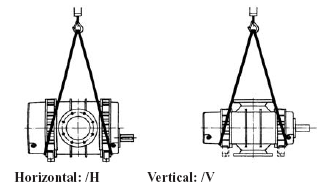
Fig. 3
3.2 Storage
Keep the blower in a dry cool closed environment. Do not remove the protective coverings placed over the blower openings. Renew the preservation every 6 months, or more frequently if the climate is damp.
3.2.1 Bearing storage
Half fill the sumps with anti-rust oil. Manually rotate the blower shaft. Dispose of the used oil in accordance with local regulations.
3.2.2 Preservation of the compression chamber
Remove the protective coverings from the blower openings. Apply a thin film of anti-rust oil to the internal surfaces of the body to the covers and to the rotor surfaces.
WARNING: Use anti-rust and foam inhibiting oil with fire point over 392ºF (200ºC) only.
| Shiny External Parts | Rust Ban 343 EXXON |
|---|---|
| Compression Chamber | Rust Ban 343 EXXON |
4.1 On-site positioning of blower
The blower has to be set horizontally on a level surface and attached using bolts which secure the feet or the outlet flange. Place shims under feet of blower to prevent overstressing of the housing
Changing the inlet/outlet arrangement
To move from the arrangement with inlet and outlet on a vertical axis to that with inlet and outlet on a horizontal axis and vice versa, exchange the oil levels by changing the position of the plugs in accordance with fig. 4.
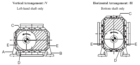
Fig. 4
| Letter | Description |
|---|---|
| A | Left Foot |
| B | Right Foot |
| C | Oil fill plug |
| D | Oil drain plug |
| E | Oil level sight glass |
4.3 Coupling
4.3.1 Direct coupling
Slide the half couplings onto the shaft of the blower and of the motor using suitable tools.
WARNING: Do not use a hammer to slide on the half couplings.
Secure the half couplings with security dowels which will push on the keys.
- Place the blower at the distance from the motor indicated by coupling manufacturer.
- Align the shafts of the blower and of the motor and, where necessary insert shims under the feet of the motor and/or blower.
- Check the alignment by using calipers or gauges as per coupling manufacturer’s specifications.
4.3.2 Belt drive coupling
Use suitable equipment to mount the sheaves onto the blower and motor shafts. The minimum blower sheave diameters are shown in Table IV.
WARNING: Do not use a hammer to mount the sheaves.
Mount the drive belts. Belt tension is produced by using the motor thrust screws in accordance with the values shown in Table V. During this phase, the alignment of the sheaves must be checked using a scale resting against the sheaves as shown in figure 5.
WARNING: Excessive belt tension could damage the blower and the motor.
Secure the feet of the motor
| Letter | Differential Pressure [psig / kPa] | |||||||||||||||||
|---|---|---|---|---|---|---|---|---|---|---|---|---|---|---|---|---|---|---|
| 3 | 207 | 5 | 345 | 6 | 414 | 7 | 483 | 8 | 552 | 10 | 689 | 12 | 827 | 13 | 896 | 15 | 1034 | |
| TL10 | 3.20 | 80 | 3.20 | 80 | 3.15 | 80 | 3.20 | 80 | 3.20 | 80 | 3.20 | 80 | 3.20 | 80 | 3.20 | 80 | X | X |
| TL20 | 3.20 | 80 | 3.20 | 80 | 3.15 | 80 | 3.20 | 80 | 3.20 | 80 | 3.20 | 80 | 3.20 | 80 | 3.20 | 80 | 3.20 | 80 |
| TL30 | 4.00 | 100 | 4.00 | 100 | 4.00 | 100 | 4.00 | 100 | 4.00 | 100 | 4.40 | 112 | 4.40 | 112 | 4.40 | 112 | 4.40 | 112 |
| TL40 | 4.00 | 100 | 4.00 | 100 | 4.00 | 100 | 4.00 | 100 | 4.40 | 112 | 4.40 | 112 | 4.40 | 112 | 4.40 | 112 | 4.40 | 112 |
| TL41 | 4.00 | 100 | 4.00 | 100 | 4.00 | 100 | 4.40 | 112 | 4.40 | 112 | 4.40 | 112 | 4.40 | 112 | X | X | X | X |
| TL50 | 4.70 | 118 | 4.70 | 118 | 470 | 118 | 5.20 | 132 | 5.20 | 132 | 5.50 | 140 | 5.50 | 140 | 5.50 | 140 | 5.50 | 140 |
| TL60 | 5.20 | 132 | 5.20 | 132 | 5.20 | 132 | 5.20 | 132 | 5.50 | 140 | 5.50 | 140 | 5.50 | 140 | 5.50 | 140 | 5.50 | 140 |
| TL61 | 5.20 | 132 | 5.20 | 132 | 5.50 | 140 | 5.50 | 140 | 5.90 | 150 | 5.90 | 150 | 5.90 | 150 | X | X | X | X |
| TL70 | 5.50 | 140 | 5.50 | 140 | 5.90 | 150 | 5.90 | 150 | 6.30 | 160 | 6.30 | 160 | 6.30 | 160 | 6.30 | 160 | 6.30 | 160 |
| TL80 | 5.50 | 140 | 5.50 | 140 | 5.90 | 150 | 6.30 | 160 | 6.30 | 160 | 6.30 | 160 | 6.30 | 160 | 6.30 | 160 | 6.30 | 160 |
| TL81 | 6.00 | 160 | 6.00 | 160 | 6.70 | 170 | 6.70 | 170 | 7.10 | 180 | 7.10 | 180 | 7.10 | 180 | X | X | X | X |
| TL90 | 7.90 | 200 | 7.90 | 200 | 7.90 | 200 | 7.90 | 200 | 7.90 | 200 | 9.00 | 225 | 9.00 | 225 | 9.90 | 250 | 9.90 | 250 |
| TL100 | 7.90 | 200 | 7.90 | 200 | 7.90 | 200 | 7.90 | 200 | 9.00 | 225 | 9.00 | 225 | 9.90 | 250 | 9.90 | 250 | 10.90 | 275 |
| TL101 | 7.90 | 200 | 7.90 | 200 | 7.90 | 200 | 7.90 | 200 | 9.00 | 225 | 9.00 | 225 | X | X | X | X | X | X |
| TL110 | 7.90 | 200 | 7.90 | 200 | 7.90 | 200 | 9.00 | 225 | 9.30 | 236 | 9.90 | 250 | 9.90 | 250 | 9.90 | 250 | 11.80 | 300 |
| TL120 | 7.90 | 200 | 7.90 | 200 | 9.00 | 225 | 9.30 | 236 | 9.90 | 250 | 9.90 | 250 | 11.80 | 300 | X | X | X | X |
| TL900 | 9.30 | 236 | 9.30 | 236 | 9.30 | 236 | 9.90 | 250 | 11.80 | 300 | 13.80 | 350 | 13.80 | 350 | X | X | X | X |
Check pressure rating for all blowers
| V-Belt Cross Section | Small Sheave Diameter Range | Small Sheave RPM Range | Speed Ratio Range | Recommended Deflection Force | ||||
|---|---|---|---|---|---|---|---|---|
| Minimum | Maximum | |||||||
| inches | mm | lbs | kg | lbs | kg | |||
| 3VX | 2.20 | 56 | 1200 - 3600 | 2.00 to 4.00 | 2.8 | 1.27 | 4.1 | 1.86 |
| 2.35 - 2.50 | 60 - 64 | 1200 - 3600 | 3.2 | 1.45 | 4.7 | 2.13 | ||
| 2.65 - 2.80 | 67 - 71 | 1200 - 3600 | 3.5 | 1.59 | 5.1 | 2.31 | ||
| 3.00 - 3.15 | 76 - 81 | 1200 - 3600 | 3.8 | 1.72 | 5.5 | 2.49 | ||
| 3.35 - 3.65 | 85 - 93 | 1200 - 3600 | 4.1 | 1.86 | 6.0 | 2.72 | ||
| 4.12 - 5.00 | 105 - 127 | 900 - 3600 | 4.8 | 2.18 | 7.1 | 3.22 | ||
| 5.30 - 6.90 | 135 - 175 | 900 - 3600 | 5.8 | 2.63 | 8.6 | 3.90 | ||
| 5VX | 4.40 - 4.65 | 112 - 118 | 1200 - 3600 | 2.00 to 4.00 | 9.0 | 4.08 | 13 | 5.90 |
| 4.90 - 5.50 | 124 - 140 | 1200 - 3600 | 10 | 4.54 | 15 | 6.80 | ||
| 5.90 - 6.70 | 150 - 170 | 1200 - 3600 | 11 | 4.99 | 17 | 7.71 | ||
| 7.10 - 8.00 | 180 - 203 | 600 - 1800 | 13 | 5.90 | 19 | 8.62 | ||
| 8.50 - 10.90 | 216 - 277 | 600 - 1800 | 14 | 6.35 | 20 | 9.07 | ||
| 11.80 - 16.00 | 300 - 406 | 400 - 1200 | 15 | 6.80 | 23 | 10.43 | ||
| 5V | 7.10 - 8.00 8.50 - 10.90 11.80 - 16.00 |
180 - 203 216 - 277 300 - 406 |
600 - 1800 600 - 1800 400 - 1200 |
2.00 to 4.00 | 11 13 14 |
4.99 5.90 6.35 |
16 18 21 |
7.26 8.16 9.53 |
| 8V | 12.50 - 17.00 18.00 - 24.00 |
318 - 432 457 - 610 |
600 - 1200 400 - 900 |
2.00 to 4.00 | 28 32 |
12.70 14.51 |
41 48 |
18.60 21.77 |
* If replacing 3V or 5V belts with the same belt length and same number of belts in 3VX or 5VX cross section, belt tension does not need to be increased.
NOTE: New drives designed with 3VX or 5VX belts should be tensioned at the respective deflection force value shown in above table.
Simplified V-Belt Tensioning Method
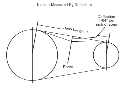
Fig. 5
Step 1– Determine the force required to deflect one belt 1/64" per inch (1/64th cm per centimeter) of span length.
Step 2– Measure the span length of your drive. Compare this deflection force with the range given in Table V.
If it is less than the minimum recommended force, the belts should be re-tensioned.
If it is more than the maximum recommended force, the drive is tighter than it needs to be.
4.4 Direction of rotation – air flow direction
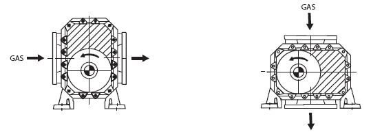
Fig. 6
WARNING: Do not use the blower with a direction of rotation or a flow direction which differs from that shown in figure 6.
4.5 System piping
The diameters of the system piping must never be smaller than the diameters of the blower openings. If the diameters are different, use a taper connector. The system piping should be properly aligned and supported to prevent placing stress on the blower. Provide flexible joints. The pipes must be thoroughly cleaned before connection. The gaskets must not interfere with the gas system.
WARNING: Remove the protective covers from the blower openings before connecting the pipes.
4.5.1 Inlet pipe
- Connect a silencer directly to the inlet of the blower.
- Thoroughly clean.
- If necessary install a dirt filter for the first 100 working hours.
- Install a pressure gauge to check the dirt filter.
- Support the pipe.
4.5.2 Outlet pipe
- Connect a silencer directly to the outlet of the blower.
- Support the piping at the point nearest to the flexible coupling.
- Insulate the pipes so as to avoid heating the environment and as a precaution to accidental contact.
4.6 Check valve
To stop the counter-rotation of the blower when it stops while loaded, install a check valve on the discharge, when acting under pressure, or on the inlet when acting under vacuum conditions.
4.7 Safety valve
To limit the maximum operating pressure of the blower use a safety valve on the discharge, when acting under pressure, or on the inlet when acting under vacuum conditions.
WARNING: Install the safety valves as close as possible to the inlet/outlet at the blower, without placing shut-off valves in-between.
4.8 Electrical connection
Use only authorized specialists to set up the electrical system, working in compliance with regulations applying to the place of installation and in accordance with the requirements of the local body supplying electrical energy. Check on the motor plate:
- Voltage
- Frequency
- Number of phases
- Absorbed current
Connect the cables as shown in the diagram accompanying the terminal box of the motor. If the diagram has not been supplied, request it from the motor manufacturer. Use electrical cables of suitable size, depending on the nominal current of the electrical motor. Keep the electric cables away from heat sources and/or pointed edges. The motor must be protected by means of an automatic switch set at the value of the rated current shown on the plate. For the safety of personnel, the system must be protected by a suitable grounding device.
WARNING: Blower service must be carried out only after disconnecting the electric supply.
5.1 Preliminary controls
If the blower has been in storage for more than 6 months, check its state of preservation.
- Check the coupling or the sheave alignment
- Check the belt tension.
- Check that the blower shaft rotates freely manually.
- Check that the safety protection devices have been correctly installed and secured.
- Fill the blower with oil as described in paragraph 6.1.1.
5.2 Start up
5.2.1 First start-up
WARNING: During this operation personnel are in direct contact with the blower, and for this reason noise protection must be worn.
- Open the shut-off valve.
- Check that the safety valve has been set at the operating value.
- Check the rotation by ‘jogging’ the motor.
WARNING: Do not rotate the blower in the wrong direction for more than a few revolutions.
- Start the blower
- Increase the operating pressure gradually until the rated value is reached.
- After about 10 to 20 minutes check that there are no oil leakages and strange noises or vibrations. If such problems are found, stop the blower immediately.
5.2.2 Normal start-ups
With direct start-up the motor starts even with the maximum discharge counter-pressure. With star-delta start-up, on the other hand, or with the starter; the counter-pressure must be zero.
5.3 Operating checks
5.3.1 Daily checks
With the blower running, check:
- Outlet temperatures.
- Discharge pressure (when functioning under pressure).
- Suction pressure (when functioning in vacuum conditions).
- Absorbed power.
5.3.2 Check after first 50 hours
With the blower shut down, check:
- The oil level.
- Oil leaks.
- Auxiliary circuit leaks.
- Belt tension.
5.3.3 Check every 500 hours
With the blower shut down, check:
- The oil level.
- Oil viscosity and condition.
- Belt wear.
- Flexible coupling inserts.
- Auxiliary circuits.
5.4 Stopping the blower
- If possible, remove the counter-pressure
- Stop electric supply.
The blower can also be stopped in the presence of the counter-pressure but, because of the high current absorption of the electric motor; problems with the electric circuit could result.
WARNING: Check that the deceleration of the blower is even and without vibrations.
6.1 Preventive maintenance
6.1.1 Oil change
The first oil change should be performed after 100 working hours. Further oil changes are performed every 2000 working hours. Oil should be checked regularly and oil changes made more frequently if lubricant becomes contaminated due to adverse conditions.
The type of oil is shown in paragraph 10.
WARNING: Dispose of the used oil in accordance with the local regulations.
WARNING: Regardless, stick to the half way mark on the oil level sight glass.
| Blower Size | Oil quantity: Vertical (qts/ L) | Oil quantity: Horizontal (qts / L) | ||||||||||
| 1 | 2 | Total | 1 | 2 | Total | |||||||
| TL10-20 | 0.33 | 0.31 | 0.71 | 0.67 | 1.04 | 0.98 | 0.22 | 0.21 | 0.44 | 0.41 | 0.66 | 0.62 |
| TL30-40-41 | 0.6 | 0.56 | 1.11 | 1.05 | 1.7 | 1.61 | 0.4 | 0.38 | 0.76 | 0.72 | 1.16 | 1.1 |
| TL50-60-61 | 0.85 | 0.8 | 1.75 | 1.65 | 2.6 | 2.45 | 0.57 | 0.54 | 1.1 | 1.04 | 1.67 | 1.58 |
| TL70-80-81 | 1.67 | 1.58 | 3.3 | 3.11 | 4.97 | 4.69 | 1.11 | 1.50 | 2.11 | 2.0 | 3.22 | 3.05 |
| TL90-100-101 | 3.2 | 3.0 | 5.8 | 5.5 | 9.0 | 8.5 | 1.8 | 1.7 | 3.44 | 3.25 | 5.24 | 4.95 |
| TL110-120 | 4.23 | 4.0 | 9.0 | 8.5 | 13.23 | 12.5 | 2.64 | 2.5 | 5.3 | 5.0 | 7.94 | 7.5 |
| TL900 | 9.5 | 9.0 | 19.0 | 18.0 | 28.5 | 27.0 | 6.34 | 6 | 10.6 | 10.0 | 16.94 | 16.0 |
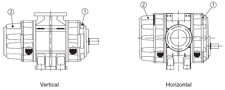
Fig. 7
7.0 Troubleshooting
| Cause | Remedies | |
| 7.1 | Inlet pressure different from the design value | |
|---|---|---|
| Inlet piping is clogged Rotation speed is not the same as design RPM |
Check piping and remove
obstruction Check rotation speed and reset to design RPM |
|
| 7.2 | Outlet pressure different from the rated value | |
| Outlet piping is clogged Rotation speed is not the design RPM |
Check piping and remove
obstruction Check rotation speed and reset to design RPM |
|
| 7.3 | Outlet temperature different from the rated value (stop the blower immediately) | |
| Inlet temperature different from
design value Compression ratio is not the same as the design conditions Rotors are worn |
Check inlet temperature
and reset to rated value Check inlet and outlet pressures and reset to rated values Measure clearances of rotors |
|
| 7.4 | Power absorbed different from the rated value | |
| Differential pressure different
from rated value Speed of rotation is not the same as rated value Incorrect electrical connection Rotors making contact |
Check the inlet and
outlet pressure and reset to rated value Check the speed of rotation and reset to rated value Check electrical system Stop blower immediately (see paragraph 7.3) |
|
| 7.5 | Loss of oil | |
| Drive shaft seal is worn Oil drain and level plugs gaskets are worn Oil level sight glasses are broken |
Replace the drive
shaft seal Replace the gaskets Replace sight glasses, fill with oil |
|
| 7.6 | High oil temperature | |
| Oil level too high Oil too viscous High differential pressure Oil produces foam |
Reset correct oil level
(see paragraph 6.1.1) Use less viscous oil See paragraph 7.2 Change the type of oil |
|
| 7.7 | Unusual noises and/or vibrations (stop the blower immediately) | |
| Differential pressure exceeds
rated value Discharge temperature exceeds rated value Rotors making contact Scale on internal parts Bearings are worn Intake of foreign particles |
Check inlet and outlet
pressures and reset to rated values see paragraph 7.3 Stop blower immediately, measure gear and rotor clearances Thoroughly clean the rotors and compression chamber Measure bearing clearances and, if necessary, replace them Remove foreign particles, clean the inside of the blower |
|
8.1 Blower disassembly
Disassembly of the blower within the warranty period results in the cancellation of the warranty.
Disassembly repair work and reassembly of the blower must be carried out only by skilled personnel and with the aid of suitable equipment and the relevant manual. This manual contains only the instructions for preventative maintenance. For any references to components see attached sections.
NOTE: The warranty does not cover damages caused by operations carried out incorrectly during disassembly and/or reassembly of the blower.
WARNING: Before starting disassembly of the blower, make sure that the power has been disconnected. Follow the instructions in paragraph 9.2.
Disassemble the drive components (sheave or coupling), following the manufacturer's instructions if there are locking devices or by means of an extractor if attached directly onto the shaft.
WARNING: Do not hammer the shaft, coupling or sheave.
Personnel who may come into contact with the blower must observe the most elementary safety rules in order to minimize the possibility of suffering physical injury With this in mind, all personnel who work in or pass through the area where the blower is functioning must be instructed in the safety rules to follow and must be warned through the use of danger notices.
9.1 Blower in operation
- Do not touch the external surfaces of the blower because they could reach temperatures higher than 285ºF (141ºC) and therefore cause burns.
- Do not hold objects or insert limbs into the blower openings because the moving rotors could cause serious physical injury.
- Provide suitable protection devices for the coupling and/or drive belts.
- If the blower is operating disconnected from system piping, place a screen in front of the inlet and keep away from the blower outlet flow.
- Do not open the oil plugs.
- Do not turn off the safety systems which are provided.
- Do not stand too close to the safety valve discharge.
- Avoid prolonged exposure to the noise produced by the blower, if suitable protection is not worn. The sound pressure near the blower could be greater than 85 dB (A)
9.2 Before any blower service
- Disconnect the electrical supply cables.
- Bring the unit to atmospheric pressure.
Stop the blower by disconnecting the electrical supply.
WARNING: The gas contained in the blower may be hot, toxic and irritant.
9.3 During blower service
- Check that all operations described in Paragraph 9.2 have been completed.
- Use adequate equipment and procedures to disconnect and handle the system piping.
- Use adequate equipment to disassemble the blower components.
- Use adequate equipment and procedures to hoist the blower and its main parts. The weight could exceed 66 lbs (30 kg).
10.1 Oil type
| Oil Type | ISO Class | Acc. To |
|---|---|---|
| Mineral oil for general use | C, CL, CLP | DIN 51517 |
| Mineral oil for hydrostatic and hydrodynamic circuits | H, HL | DIN 51524 |
| Mineral oil for internal combustion engines | HD | |
| Synthetic oil |
10.2 Oil viscosity
| ISO Class | USE |
|---|---|
| ISO - VG 150 | oil temperature up to 176ºF (80ºC) compression ratio up to 1.7 gas discharge temperature up to 230ºF (110ºC) ambient temperature up to 95ºF (35ºC) |
| ISO -VG 220 | oil temperature up to 230ºF (110ºC) compression ratio higher than 1.7 gas discharge temperature up to 230ºF (110ºC) ambient temperature higher than 95ºF (35ºC) installation in soundproof enclosure |
10.3 Recommended oils
| Make | Type | ISO VG - 150 | Pour point | ISO VG - 220 | Pour point | ||
|---|---|---|---|---|---|---|---|
| °F | °C | °F | °C | ||||
| Exxon | Nuto | 150 | 0 | -18 | 220 | 0 | -18 |
| Mobil | D.T.E. | Extra Heavy | 16 | -9 | BB | 20 | -7 |
| Pennzoil | Pennzbell | R + O 150 | 15 | -9 | R + O 220 | 15 | -9 |
| Shell | Tellus | C 150 | 0 | -18 | C 220 | 5 | -15 |
| Texaco | Regal | R + O 150 | 12 | -11 | R + O 220 | 12 | -11 |
| Mobil | Synthetic | SHC629 | -49 | -45 | SHC630 | -49 | -45 |
10.4 Minimum working temperature
Check that the pour point of the oil is less than the minimum temperature that can be reached in the ambient If this is not the case, select an oil with a lower viscosity (a g.: ISO VG-100), or use an oil specially made for low temperatures according to recommendations of oil producers.